Jump to a question in this guide
- How does heat get from its source into this room?
- Are all heated floors electric or water-based?
- How do the main water-heated floor constructions compare?
- Tubing in a slab: why is the concrete part of the heater?
- Thin overpour: what is added above the existing floor?
- Dry grooved panels: how does the heat reach the finish?
- Below-floor contact plates: why does contact with the deck matter?
- Suspended tubing on clips: what does the airspace change?
- Does one loop mean one room or one thermostat zone?
- What do the circulator, zone valve and actuator each do?
- How does a radiator transfer heat into the room?
- What is inside hot-water baseboard heating?
- Where do fan-coils and air handlers fit into hydronic heating?
- Why can a heat request and room warming happen at different times?
- Why is a warm pipe different from heat delivered to the room?
- What can you record safely about a cold or uneven room?
- Which conditions need prompt assistance?
- What should a repair or renovation scope explain?
- How do a different heat source and running costs change the decision?
- What are the most useful questions to keep with the system?
- Heat source, circulation, controlled route, emitter and room response have different jobs.
- Slab, overpour, dry panels, contact plates and suspended tubing need individual explanations.
- A room, a fluid loop and a thermostat zone need not be the same boundary.
- Radiators, hot-water baseboards and fan-coils remain part of hydronic heating.
- A warm pipe or source invoice is not by itself a room-delivery assessment.
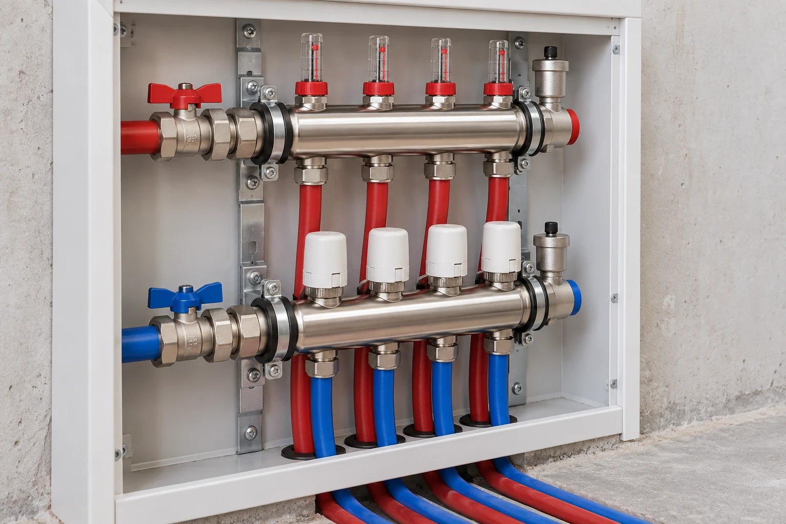
The manifold divides supply among branches and collects returns. Four paired loops are illustrated; actuator leads and the rest of the operating controls are omitted. Pipe colours do not prove actual flow.
About this illustration
12 picture lessons appear beside the questions in this guide. Use them to understand the explanation, then consider what it means for your home.
How does heat get from its source into this room?
One bedroom is cold while the rest of the house is comfortable. Or the bathroom floor warms eventually, but not when you expect it. That does not automatically mean the boiler is too small or broken. Heat has to reach the room through several connected parts, and the room has to hold enough of what arrives.
In a typical pumped hydronic arrangement, the heat source warms circulating fluid. A circulator moves it through piping. A radiator, baseboard, floor or other emitter transfers heat toward the room, and the fluid returns along its route. Hydronic describes the water-based distribution; it does not name the fuel or prove that the source is a boiler.
The thermostat asks for a condition at its own location. Controls decide how the identified system responds. Valves or actuators can govern particular routes, while the circulator moves fluid. A heat request is therefore different from measured circulation and different again from heat reaching a distant room.
Follow the first picture all the way back to the source. Every illustrated supply route needs a return; water does not disappear into a radiator or flow into the room air. The example is a mechanism map, not a complete plumbing or electrical schematic for your house.
Once that route is clear, it becomes easier to understand the floor variants and the exposed emitters. The useful service question is which link needs attention: source, controls, circulation, emitter or room heat loss. A recent source-service invoice may answer one of those while leaving the cold-bedroom question open.
One distribution point can serve several loops
The manifold divides supply among branches and collects returns. Four paired loops are illustrated; actuator leads and the rest of the operating controls are omitted. Pipe colours do not prove actual flow.
Choose a part name to highlight its explanation below.
- Supply branches
The upper bar distributes fluid among illustrated branches.
- Return branches
The lower bar collects returning fluid.
- Actuator heads
These operate compatible valves, with electrical leads and control logic omitted.
Are all heated floors electric or water-based?
Electric resistance floors make heat in a manufactured electrical heater. Hydronic floors receive heat through fluid circulating in tubing. The floor finish can look the same in both cases. An invoice, identified product and available layout are more useful than deciding from a warm tile or a familiar thermostat shape.
The electric companion guide shows separate cable, mesh, shaped-carrier, foil-wire, film and below-subfloor mat arrangements. Here the main story is the water route and what its floor construction or room emitter does with the heat. Neither distribution family has one universal running cost or an automatic capacity for every room.
There are also proprietary engineered alternatives. Legalett’s manufacturer FAQ describes an air-heated slab with a closed heating-air loop and an electric heater or water-to-air coil. That heating loop is separate from room ventilation. It is a named example showing why a two-family summary is not a catalogue of every floor product.
The air-slab FAQ contains older marketing and approval language that is not independently verified here. It supplies no general saving, structural approval, maintenance-free promise or substitute design for another house. If that is the actual installed system, its own engineering, model and operating information matter.
For a water-based system, next identify where the tubing sits and what supports the finished surface. A slab, an added pour, a dry panel and a below-floor arrangement put different materials in the heat path. They should receive their own explanation, rather than one picture labelled radiant floor.
How do the main water-heated floor constructions compare?
The early comparison separates five common construction examples: tubing embedded in a slab; tubing in a separate overpour above a supporting deck; dry grooved panels; below-subfloor tubing in contact plates; and tubing suspended on clips with an airspace. The last two are different arrangements, not interchangeable drawings of the same thing.
Ask where the tube is, which material spreads its heat and which part supports the floor. Then ask what the finish and room need. A drawing that makes every layer look like concrete can hide an existing timber deck; a drawing that suspends a plate away from the subfloor can miss the central contact relationship of the named plate system.
These choices affect construction coordination, height, access, response and the way the room’s heat requirement is met. They do not establish a universal cheapest, fastest or most efficient floor. The designer still has to match the actual assembly, finish, heat source, water conditions and room demand.
Use each individual study below to understand its practical attraction, constraints and issues. No tube spacing, slab thickness, water temperature, floor resistance or installation dimension is supplied as a Canadian default. A named manufacturer example teaches the parts; the actual project still needs its complete applicable design.
Five water-heated floor constructions
- Tubing embedded in a slabTube transfers heat into substantial concrete and then the surface. Broad heated area and useful heat storage in a suitable design. Response, concealed access, support/insulation and finish need coordinated design. Which slab area is heated, and how does its construction meet the room’s need?
- Tubing in an added overpourA separate heated topping lies above a supporting deck. Embedded heating can suit an appropriate suspended or renovated floor. Added load/height, topping moisture/curing and covering coordination. What supports the added layer and which topping/finish combination is specified?
- Dry grooved panelTube transfers heat through its specified channel/spreading assembly. The named panel avoids a wet overpour. Panel identity, support, finish-specific layers and output still matter. Is this aluminium-XPS or another panel type, and what goes above it?
- Below-subfloor contact plateTube seats in a metal plate against the underside of the deck. Possible retrofit from suitable accessible joist spaces. Contact, deck/finish resistance, access and insulation affect the actual design. How is the plate-contact route through the existing floor assessed?
- Clip-only suspended tubingTube hangs below the deck with a designed airspace, not a contact plate. A separate documented method avoiding an upper pour. Its heat-transfer route cannot be assigned contact-plate performance. Which suspended method and room-output assessment apply here?
These researched examples explain different constructions. Confirm the exact product, complete assembly and local requirements for the actual home.
Further reading: Uponor · Residential Radiant and Hydronics Installation Handbook, 7th edition December 2023; Caleffi · 8: Heat Emitter Options; Uponor · XpressTrak Installation Guide; Uponor · JoistTrak Heat Transfer Panel Handbook.
Tubing in a slab: why is the concrete part of the heater?
In this example, tubing is embedded within concrete. Heat passes from the circulating fluid through the tube into surrounding material, then toward the finish and room. The slab is part of the thermal route, not simply a support with a heater stuck underneath it.
A substantial heated surface and useful heat storage can suit an appropriately designed building. The same stored energy also affects response. Changing the heat input does not instantly change the temperature of the whole slab or the occupied room. That characteristic has to be considered with the household’s intended operation.
Insulation beneath and at the edge addresses routes where heat could leave in less useful directions. Its actual specification belongs to the building and floor design. The conceptual cutaway does not provide a complete structural slab, reinforcement design, joint detail or a universal insulation arrangement.
Concealed tubing makes later work important. Fastening, saw-cutting or altering the slab needs knowledge of the actual system and a suitable professional plan. A surface crack, stain or cool patch does not locate a leaking tube or establish that the heating system caused the observation.
Before buying or renovating, ask which slab areas are heated and what layout, construction and commissioning information is available. For a comfort concern, connect that construction with the actual flow, controls and room demand. A visible concrete floor alone cannot explain which of those questions remains open.
Concrete stores and spreads heat from the tubing
Tubing carries heated fluid through the slab, while concrete spreads and stores heat. Concrete is removed in this illustration to reveal the tube; the picture specifies no depth, spacing or room output.
Choose a part name to highlight its explanation below.
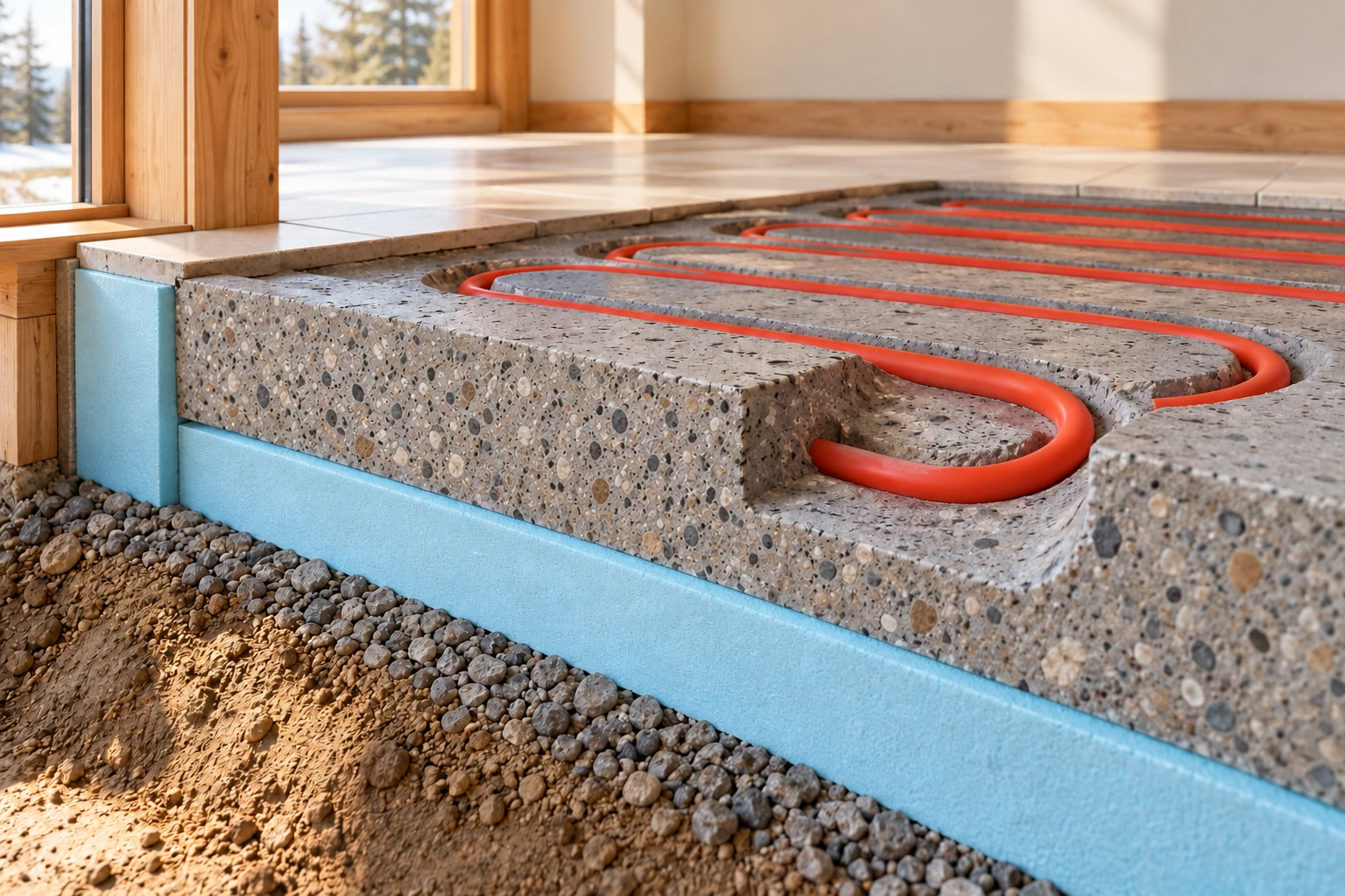
- Tubing
The continuous route carries the heating fluid.
- Concrete
The surrounding mass spreads and stores heat.
- Lower layers
The selected cutaway includes insulation and a supporting base.
Thin overpour: what is added above the existing floor?
An overpour is a separate layer containing tubing above a supporting floor or deck. In the illustrated timber-floor example, the existing deck supports the added build-up; the topping surrounds the tubing and helps spread heat toward the finish. Those are different physical jobs.
This can bring an embedded broad-surface heating arrangement to a suitable suspended floor or renovation. It does not require the old floor to become the same object as a structural concrete slab. The picture should make the boundary between existing support and new heated topping easy to see.
The tradeoffs include added load and height. Thresholds, adjoining rooms, stairs or fixtures may need coordination, while the supporting construction still needs to suit the completed work. Thin is a description of the particular topping, not permission to skip a support or deflection review.
The material also matters. Concrete and gypsum-based underlayments have their own instructions, moisture/curing conditions and covering requirements. Do not assume that a floor looking dry establishes readiness, or switch on heating to accelerate a process from an unrelated product’s instructions.
Ask what supports the new layer, which topping and finish were specified and how the construction and heating were coordinated. If a repair is proposed, distinguish a finish or topping problem from a tubing, flow or control problem. They may involve different people and different access.
A separate poured layer above a timber deck
The separately specified poured layer contains tubing above the support deck. Its added weight, height, curing and finish requirements need coordination; this is not a universal retrofit recipe.
Choose a part name to highlight its explanation below.
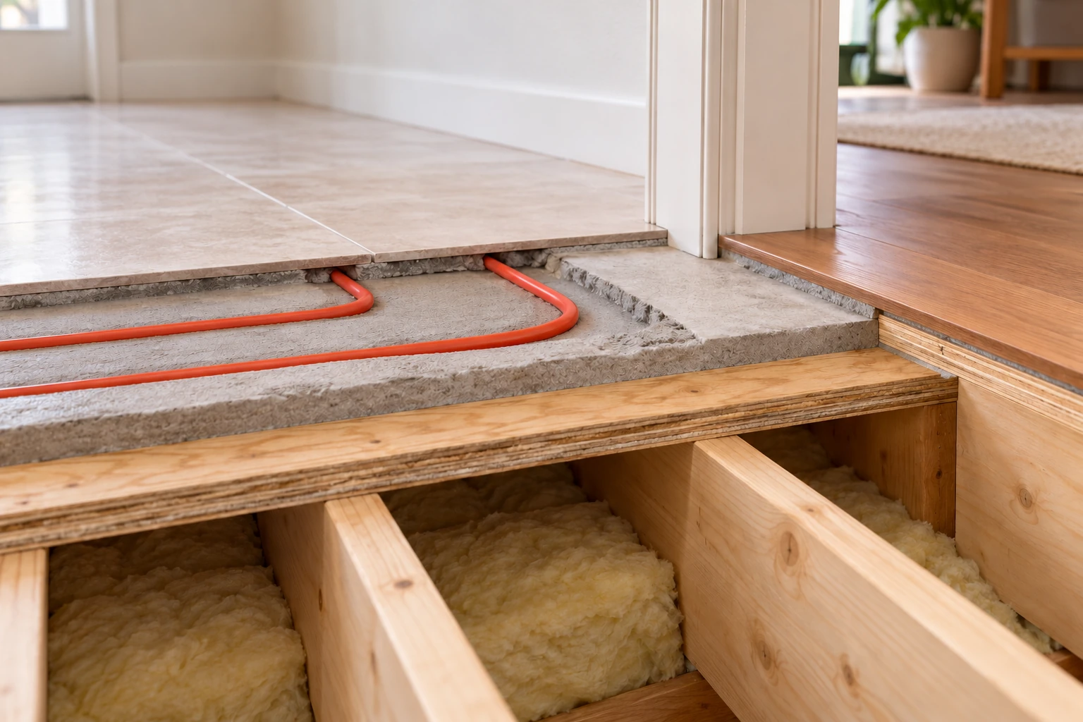
- Poured layer
The separate layer surrounds the tubing.
- Support deck
The timber deck below must suit the proposed load.
- Transition
The floor build-up affects adjoining levels.
Dry grooved panels: how does the heat reach the finish?
A dry above-deck system positions tubing in shaped channels and uses an identified heat-spreading arrangement. It avoids a wet overpour in the particular panel example. The tube, panel, heat spreader, supporting floor and covering still have separate jobs.
The pictured XpressTrak example uses aluminium-laminated XPS panels. QuikTrak is a different plywood-panel construction. Those product names should not be blended into a generic section that borrows convenient layers from both. Identify which arrangement is actually proposed.
A lighter dry arrangement can be attractive where its approved construction suits a renovation. Height, transitions, support and covering protection do not disappear. The manufacturer’s finish-specific details are part of the choice, rather than optional extras after the tubing is in place.
For the named tile example, the guide describes a compatible intervening backer or uncoupling arrangement and bonding materials above the panel. Tile is not simply placed directly onto exposed tubing. Other finishes have their own conditions; the illustration is one identified example, not a menu of interchangeable floor products.
The heat path also depends on the tube and spreading assembly functioning as designed. Damage, unsuitable covering layers, poor contact or an inadequate room design can lead to a disappointing result. Less material to warm does not by itself prove sufficient heat output or a lower annual bill.
Ask the provider to identify the exact panel, full finish build-up, intended heated area and design goal. For later flooring work, keep the actual layout and system identity available. A dry system can still be damaged or affected by work above it.
A dry grooved panel spreads heat without an overpour
This aluminum-faced foam-panel example holds tubing in grooves and spreads heat across the panel. No finished covering is shown; other dry systems and tile build-ups have different details.
Choose a part name to highlight its explanation below.
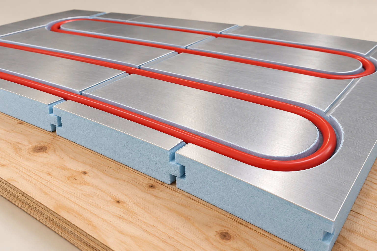
- Grooves
The shaped route holds tubing.
- Metal face
The aluminum face spreads heat.
- Supporting floor
The panel sits above its supporting deck.
Below-floor contact plates: why does contact with the deck matter?
Look upward between the joists in this example. The water tubing sits in a shaped aluminium plate against the underside of the wood subfloor. Heat moves from fluid to tube, through the plate and into the floor above. The plate gives that heat a broader contact route than the tube alone.
This is a possible retrofit approach when suitable joist spaces are accessible from below. It can be relevant where keeping the finish above is part of the plan. Access still has to account for joists, blocking, pipes, ducts and the actual construction; an unfinished ceiling is not a complete design assessment.
The plate-to-floor relationship is central to the named JoistTrak example. It is not a plate hanging well below the deck across a deliberate air gap. Insulation belongs below the heating assembly in that example. The clip-only construction in the next chapter uses a different heat-transfer route.
The existing subfloor and finish remain in the path to the room. Their resistance, the actual contact and the designed fluid conditions affect delivery. A plate drawing does not establish that every timber floor can meet its full room load at one standard water temperature.
Poor contact, an incompletely addressed heat route or an unsuitable design can affect comfort. Thermal movement can also contribute to noises that need assessment; a tick is not automatically evidence of leakage. Describe when the sound or comfort change occurs without touching hot equipment, removing insulation or altering valves.
The practical question is: “How does this actual tube-and-plate arrangement deliver the required heat through my existing floor?” Ask which construction and performance questions the proposal covers, and how any affected ceiling or floor access will be restored.
Contact plates meet the underside of the floor
The tube meets the plate channel, and the plate wings contact the underside of the deck. Insulation lies below. This contact route differs from the separate suspended-tube method.
Choose a part name to highlight its explanation below.
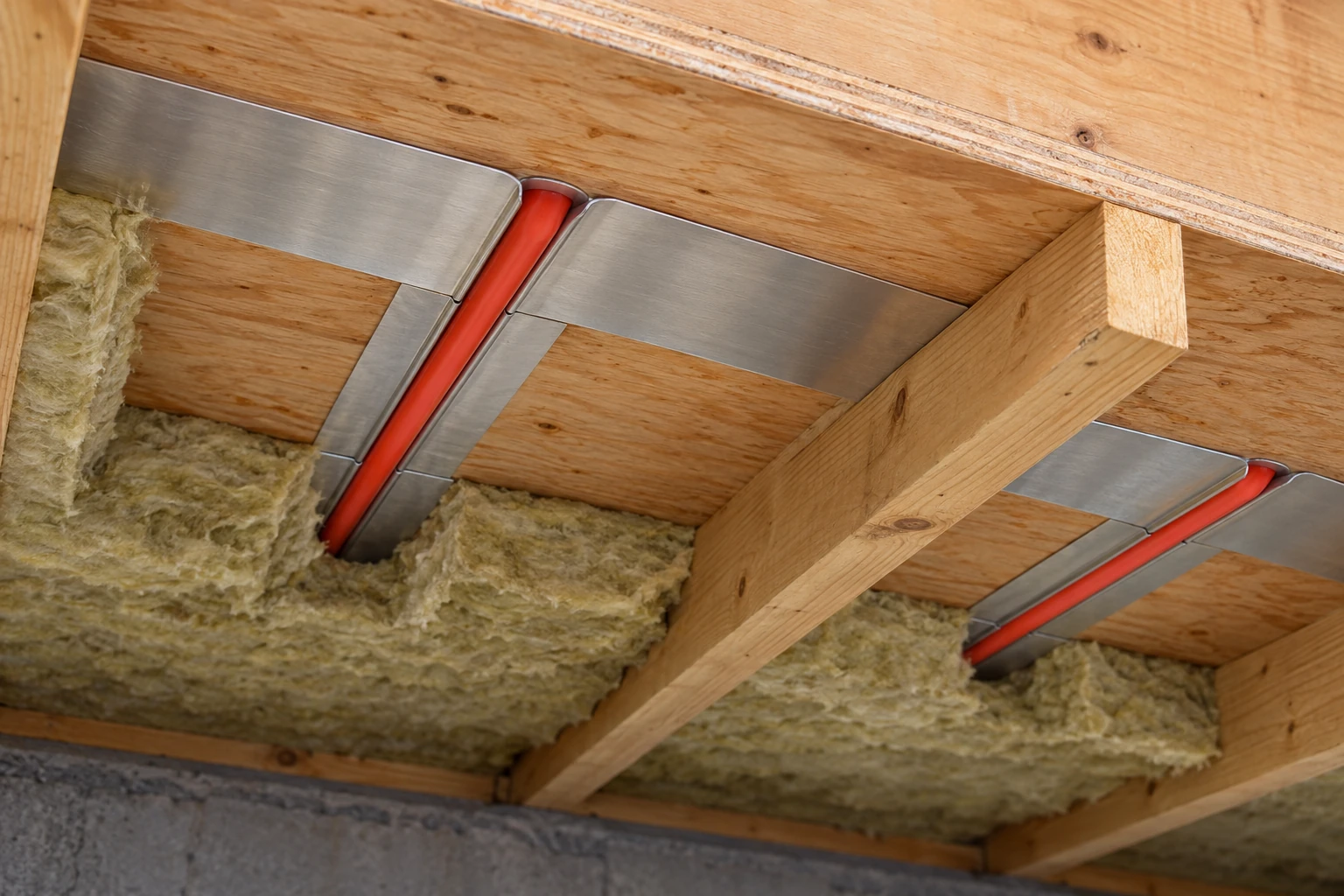
- Tube and channel
The seated tube transfers heat to the plate.
- Plate wings
The wings contact and spread heat into the deck.
- Insulation
The illustrated insulation lies beneath the assembly.
Suspended tubing on clips: what does the airspace change?
In the named clip-only method, clips fasten to the underside of the subfloor and suspend the tubing below it with a designed airspace. There is no broad metal plate providing the contact route shown in the previous chapter. Heat released in the joist space reaches the floor by that different arrangement.
This is another documented below-floor method that can avoid adding a poured layer above. The supporting construction, insulation and treatment of the heated bay remain part of its design. It should not be presented as plate-contact construction with the plate merely left out of the artwork.
The named JoistTrak guide describes its contact plates as improving heat transfer compared with staple-up installations. That comparison can affect the designed water conditions and available output. It does not supply a temperature setting for your home or prove that every existing clip-only installation needs replacement.
Air leakage, insulation, obstructions and the room’s heating requirement are important questions. A room that receives too little heat will not be understood by assuming that its suspended tubing performs like an unrelated plate system. Have the provider identify the actual method before proposing a change.
Keep this distinction in mind when looking at accessible construction photographs. Ask whether tubing is plate-connected or intentionally suspended and which design was used. Do not move tubing, add plates or pack insulation around it to make the picture match another system.
Suspended tubing leaves an intentional airspace
In this researched suspended-tube example, underside-deck clips hold the tube in an airspace. It has no contact plates; hanger spacing, gap and heating output are not specified by the illustration.
Choose a part name to highlight its explanation below.
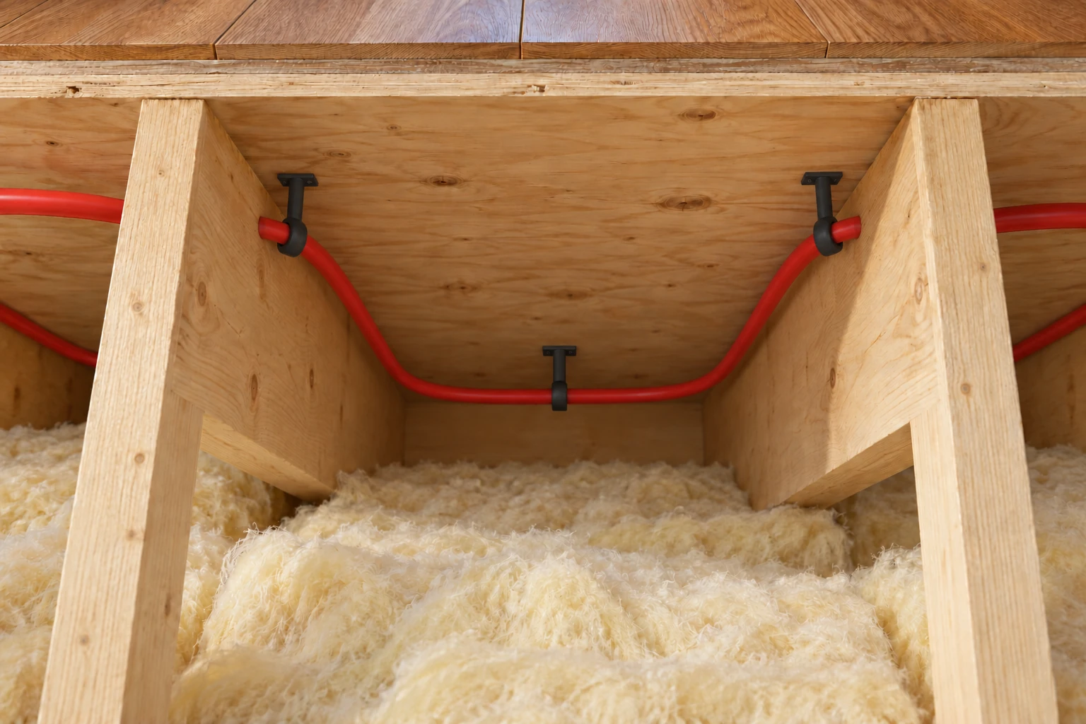
- Hangers
The supports attach to the underside of the deck.
- Airspace
The tube is held below the plywood rather than seated in a contacting plate.
- Insulation
The lower insulation belongs to the selected arrangement.
Does one loop mean one room or one thermostat zone?
A loop is a physical fluid route. A control zone is an area governed by an identified control arrangement. A room is a space people occupy. Those three boundaries do not always coincide, so a handwritten upstairs label is useful context but not a complete map.
A manifold can distribute supply fluid into several branches and collect their returns. Several floor loops can serve one controlled area, while different spaces may have their own controls or actuators in another design. Follow the actual connections and control relationships rather than assigning one room to every visible branch.
Not every hydronic system uses separate manifold branches. In a series loop, fluid passes through successive emitters before returning, releasing heat along the way. Downstream conditions and the effect of a proposed change therefore depend on the circuit. A picture of independent branches cannot identify a real series circuit.
This matters when an addition, divided room or floor conversion changes the use of the building. The thermostat may still observe one location while several rooms and emitters share a route. The right conversation may concern the map, room loads and controls—not simply a new thermostat for the room that feels cold.
Ask the provider to identify which rooms and emitters each thermostat serves, where the loops go and what remains uncertain. Keep any actual drawing with the system information. Do not establish the map by turning unfamiliar valves, disconnecting thermostats or changing several room settings as an experiment.
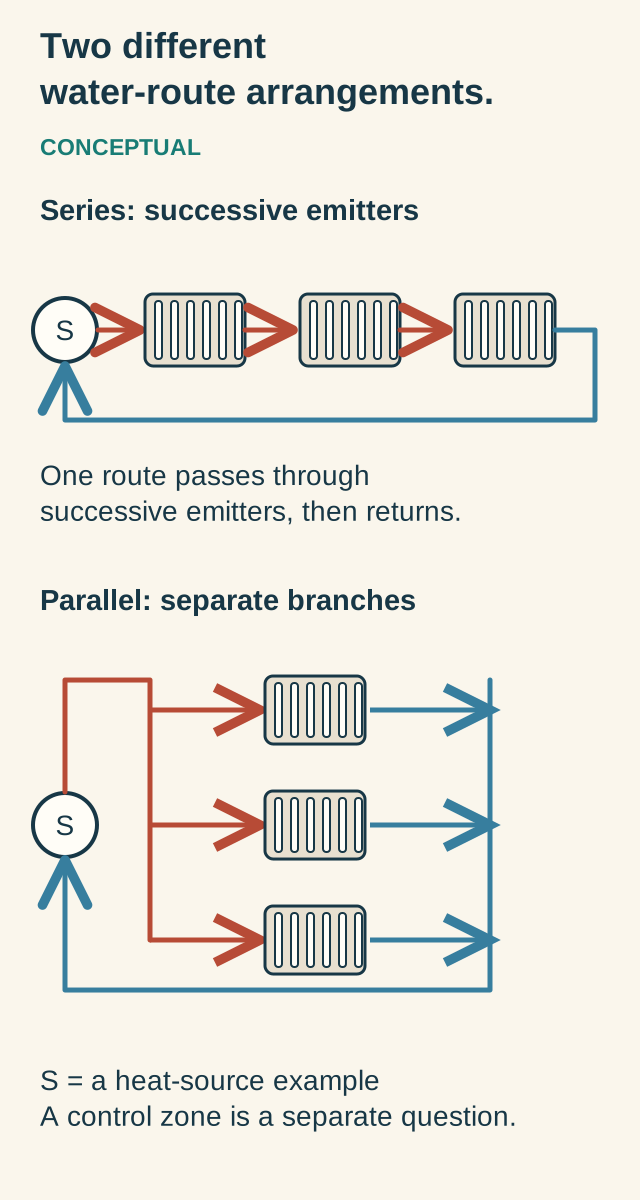
Two different water-route arrangements.
A series route serves successive emitters; parallel branches connect to shared supply and return. The actual pipe and control map determines which arrangement serves the home.
Choose a part name to highlight its explanation below.
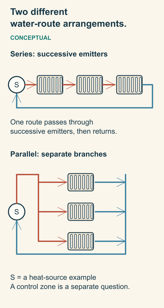
- Series
Fluid passes through successive emitters before returning. Conditions downstream depend on the actual circuit.
- Parallel
Separate branches connect supply and return in this conceptual example.
- Zone and room
A physical loop, an occupied room and a thermostat zone need not be the same boundary.
- Use
This is not a plumbing schematic or instruction to alter valves, pumps or controls.
Two different water-route arrangements.
A series route serves successive emitters; parallel branches connect to shared supply and return. The actual pipe and control map determines which arrangement serves the home.
- Series
- Fluid passes through successive emitters before returning. Conditions downstream depend on the actual circuit.
- Parallel
- Separate branches connect supply and return in this conceptual example.
- Zone and room
- A physical loop, an occupied room and a thermostat zone need not be the same boundary.
- Use
- This is not a plumbing schematic or instruction to alter valves, pumps or controls.
Read all the diagram text
- Two different water-route arrangements.
- CONCEPTUAL
- Series: successive emitters
- S
- One route passes through successive emitters, then returns.
- Parallel: separate branches
- S
- S = a heat-source example A control zone is a separate question.
What do the circulator, zone valve and actuator each do?
A circulator is a pump that moves the heating fluid through its intended circuit. A valve can govern a fluid route, while an actuator is the mechanism that operates a compatible control valve. A control signal and the movement of fluid are different parts of the complete sequence.
Systems can arrange those jobs differently. Some use a shared circulator with controlled branches; others use different pumping arrangements. The conceptual picture shows the relationship between demand, controlled passage and circulation. It is not a list of parts that every house must contain.
An indicator or a pump-like sound helps describe what happened, but it does not independently measure the right amount of fluid reaching a particular emitter. A warm surface is not a flow measurement either. A professional chooses suitable checks for the actual arrangement.
A fault in a control or actuator, a circulation concern and a heat-source problem can require different work. Ask what the finding supports before a pump, valve or boiler replacement is proposed. It is more useful to connect the part to the affected route than to replace the most visible component first.
Stay with ordinary dry access and intact controls. Do not adjust pump speeds, valve positions, system pressure or boiler settings to see which one changes the room. The technician should explain the intended configuration and document any justified change.
How does a radiator transfer heat into the room?
A hot-water radiator contains fluid in its intended waterways and transfers heat through its material to the room. It does not release heating water into the air. The radiator’s form, size and operating conditions influence what it can deliver.
Modern panel radiators can combine a room-facing heated surface with fins behind it that warm passing air. A panel can therefore exchange radiant heat and also support convection. The word radiator does not mean that only one heat-transfer mechanism is at work.
Older cast-iron and modern panel emitters have different forms and heat storage. A substantial emitter can continue releasing stored heat after input changes. Its appearance does not establish its current output or whether the house uses hot water, steam or an electric lookalike; system identity matters before work is planned.
Radiators can provide room heat without the same concealed floor construction, but their usable size and location still have to meet the room’s requirement under the designed water conditions. Replacing a heat source with one intended to supply different temperatures needs an emitter-and-room assessment, not an assumption that every radiator must be removed.
A visible leak, changed room pattern, obstruction or concern about hot surfaces should be described to the appropriate provider. Do not bleed, disconnect, paint internal parts or change valves as a diagnostic experiment. Ask which actual emitter and circuit were assessed and what the proposed work is intended to improve.
A steel panel radiator heats through faces and fins
The water-heated steel panels transfer heat through their faces, while folded internal fins help warm moving room air. The cutaway shows a selected construction, without proving exact internal passages or output.
Choose a part name to highlight its explanation below.
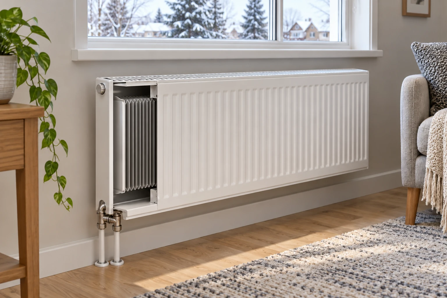
- Steel faces
The water-heated panels transfer heat toward the room.
- Folded fins
Internal folded steel increases the surface interacting with air.
- Top grille
Air can leave through the upper opening.
What is inside hot-water baseboard heating?
In a fin-tube baseboard example, warm fluid passes through a tube with attached metal fins. The fins increase the area exchanging heat with the surrounding air. Cooler room air enters near the lower opening, warms around the element and rises toward the upper opening.
The cabinet is therefore more than a decorative cover. Its intended air path works with the tube and fins. Furniture, an unsuitable enclosure, dust or damaged fins can affect the heat reaching the room. Those are reasons for an appropriate assessment, not instructions to dismantle a hot baseboard yourself.
A long low-profile emitter can suit some room layouts, but a length of cabinet does not establish a particular output. Standard and specially designed lower-temperature baseboards can have different elements and ratings. The actual model and water/room conditions must be used when evaluating a different heat source.
Hot-water and electric baseboards can look similar from across the room. Confirm the installed system through its identity and records rather than an assumption about the cover. The electric-baseboard guide addresses that separate resistance-heating arrangement.
For a cold section, report the location, room and ordinary operating pattern. Ask how the provider will distinguish circulation, emitter condition, controls and room demand. Do not feel along hot pipes, remove the cabinet or turn a valve to create a comparison.
Hot-water baseboard: tube, fins and moving air
Heated water warms the copper tube, the tube warms the fins, and room air moves through the cabinet openings. This is hot-water fin-tube baseboard, with no output or clearance promise.
Choose a part name to highlight its explanation below.
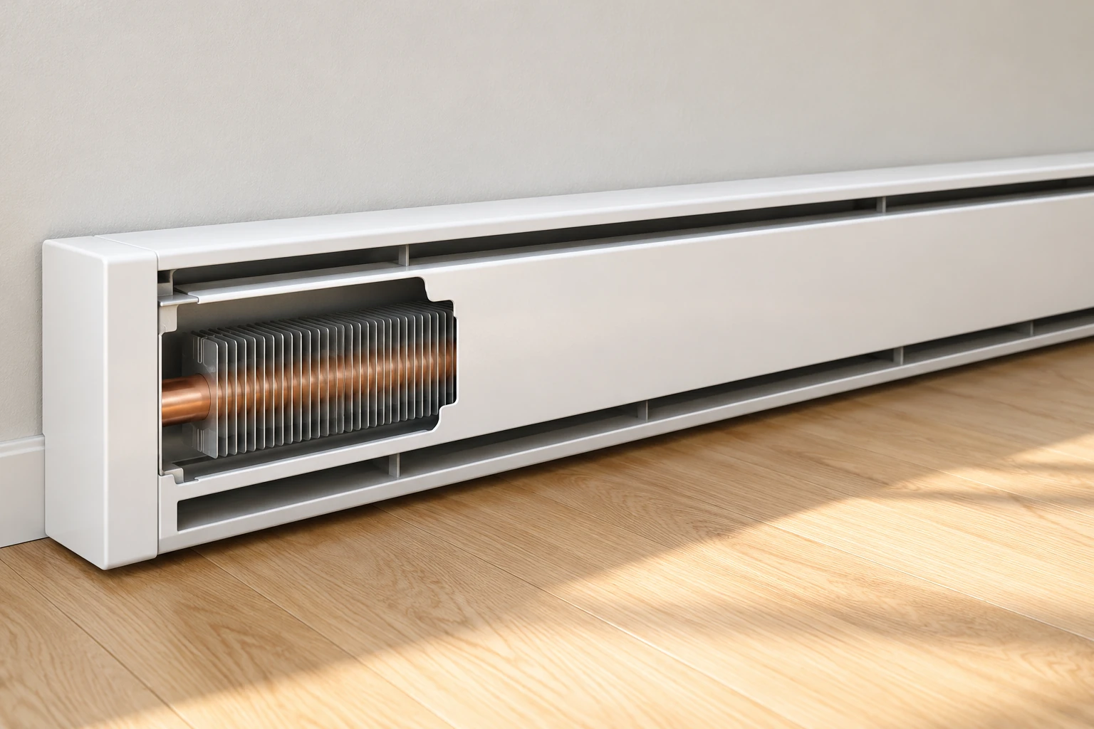
- Copper tube
The intact tube carries the heating fluid.
- Metal fins
The fins provide more surface for heat transfer to air.
- Cabinet openings
Lower and upper openings guide natural room-air movement.
Where do fan-coils and air handlers fit into hydronic heating?
A fan-coil receives heat through fluid but delivers it to the room using moving air. Fluid passes through a coil, and a fan moves air across the coil’s heat-transfer surface. That is why a water-based system can still have a grille, blower or ducted delivery component.
A smaller room fan-coil and a larger air handler can use that same broad relationship in different arrangements. The exact model determines the air path, controls and served space. Do not decide that every grille belongs to a gas furnace or that every hydronic room heats silently without a fan.
These emitters can offer different placement and delivery options from a radiator or floor. Their performance depends on both the water side and the air side. A suitable room and heat-source design still matters; merely hearing the fan is not proof of the intended water flow or heat output.
If delivery changes, note the affected room, ordinary fan/control state and what else changed. The professional may need to assess airflow, fluid conditions, controls and the actual coil. Do not open electrical covers, reach into a fan, alter dampers or treat a fan sound as a complete performance test.
Why can a heat request and room warming happen at different times?
A thermostat observes its own location and issues a request under its actual settings. The system then has to respond through controls, circulation and emitters. The room’s temperature changes over time as heat arrives, is stored in materials and leaves through the building.
Floor construction can make that sequence especially noticeable. A slab and a lower-mass panel do not store the same amount of heat, while an underfloor route has the existing deck and finish between tube and room. A slow response can fit a design characteristic, but it is not an excuse to ignore a changed or inadequate result.
Some controls coordinate other demands or continue part of a sequence after the last room request. The retained tekmar 304P example has model-specific priority and post-purge functions. Its light and timing must be read using its exact manual and configuration, not treated as universal boiler behaviour.
If discomfort seems to coincide with ordinary hot-water use, note the sequence rather than deciding that a shower caused the cold room. Ask whether the actual system shares a source and whether a relevant priority function is configured. Coincidence is a useful service question, not the diagnosis.
Keep the existing schedule alongside the observed response. A room recovering after a setback asks a different question from one that stays cold during its intended heating period. Do not adopt a universal setback, recovery time or higher-temperature setting from another installation.
Ask the provider how the actual control, emitter and room were intended to work together. A readable explanation of normal operating states is more useful than a rule that a particular icon, noise or delay always means the system is healthy.
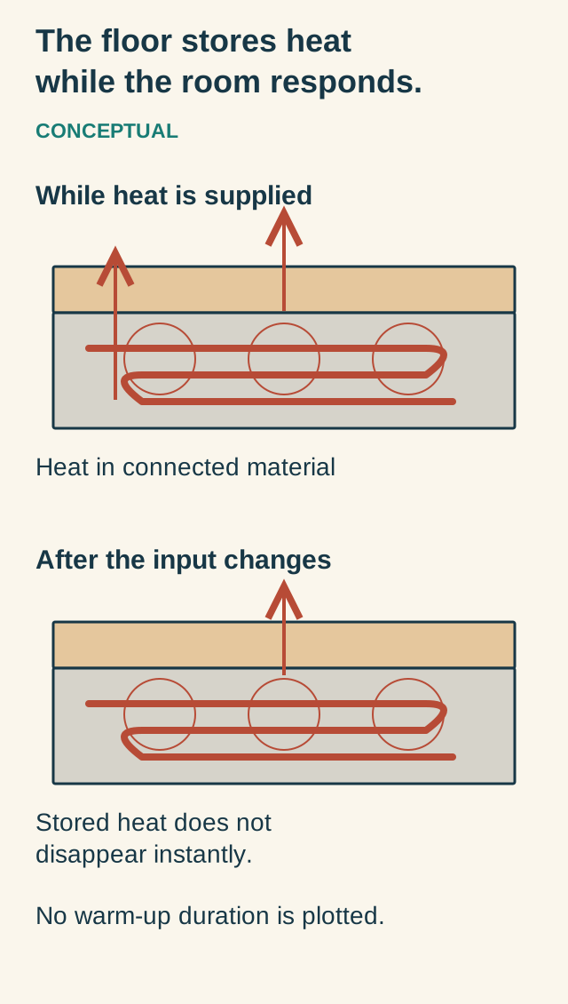
The floor stores heat while the room responds.
Connected floor material stores heat and continues exchanging it after the input changes. The actual assembly, controls and room conditions shape response; no universal delay is shown.
Choose a part name to highlight its explanation below.
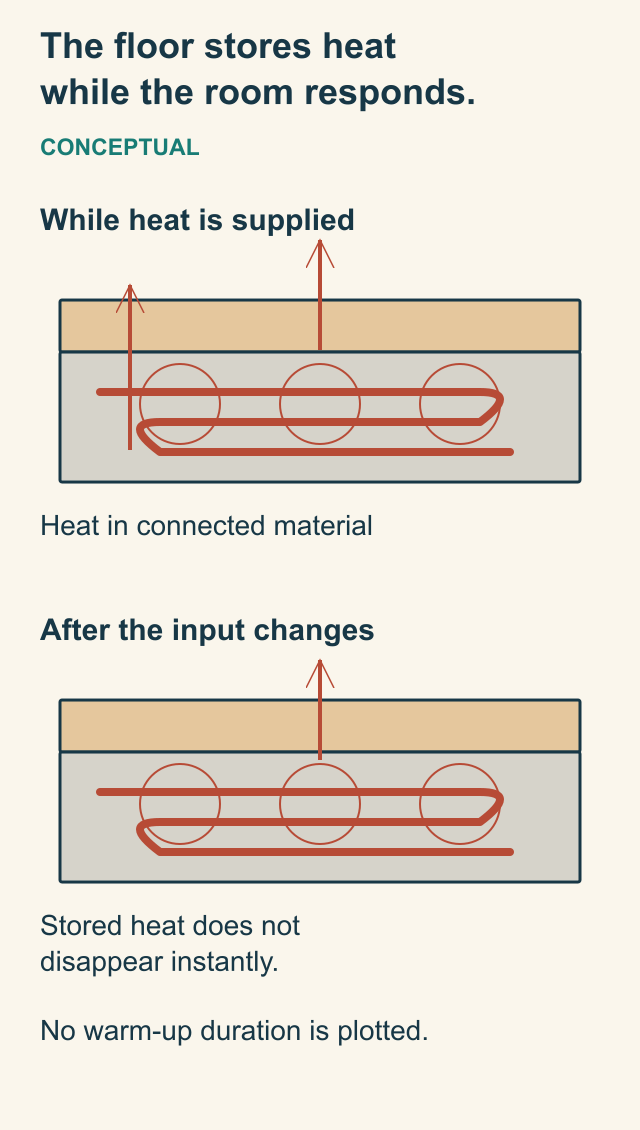
- Input
A thermostat request and the actual system response are connected but distinct.
- Storage
Heated construction stores energy and does not instantly become cold when input changes.
- Room
Room conditions change as heat arrives, is stored and leaves the space.
- Interpretation
No delay is diagnosed as normal or faulty from this conceptual sequence; no universal recovery time or operating setting is supplied.
The floor stores heat while the room responds.
Connected floor material stores heat and continues exchanging it after the input changes. The actual assembly, controls and room conditions shape response; no universal delay is shown.
- Input
- A thermostat request and the actual system response are connected but distinct.
- Storage
- Heated construction stores energy and does not instantly become cold when input changes.
- Room
- Room conditions change as heat arrives, is stored and leaves the space.
- Interpretation
- No delay is diagnosed as normal or faulty from this conceptual sequence; no universal recovery time or operating setting is supplied.
Read all the diagram text
- The floor stores heat while the room responds.
- CONCEPTUAL
- While heat is supplied
- Heat in connected material
- After the input changes
- Stored heat does not disappear instantly.
- No warm-up duration is plotted.
Why is a warm pipe different from heat delivered to the room?
Heat transported by fluid depends on how much moves and how much energy it gives up, not just whether one accessible surface is warm. A professional assessment relates flow, fluid properties and temperatures to the actual circuit and operating conditions.
Under suitable stable operating conditions, heat-transfer rate equals fluid mass-flow rate multiplied by specific heat capacity and the supply-to-return temperature difference. This relates heat transfer from the fluid across the assessed circuit; it does not, by itself, prove how much useful heat reaches each occupied room. It explains why flow and temperatures belong together without supplying the home a required flow, pressure or temperature difference.
The emitter then transfers heat according to its own relationship with the surrounding room. A radiator, fin-tube baseboard, fan-coil and floor cannot be assigned one generic output because warm water reaches each of them. Actual size, construction and operating conditions matter.
A source-service report may establish findings about the source while leaving circuit delivery unmeasured. Conversely, a room problem does not prove that the source lacks capacity. Ask which part of the route the evidence addresses and whether an emitter or room-load assessment is also needed.
Do not touch hot surfaces, remove insulation, attach improvised instruments or treat a gauge as a diagnosis. Suitable measurements need the right method, access and interpretation. The role of the equation is understanding the report, not carrying out a balancing procedure.
What can you record safely about a cold or uneven room?
Locate the concern before naming a cause. Is it the whole home, one apparent zone, a radiator, a floor area or a room far along a route? Record when it is noticed, the existing mode or schedule and whether other rooms follow the same pattern.
Keep ordinary conditions with the account: weather, occupancy, direct sun near a thermostat, a changed floor covering, furniture or recent work. Rooms can have different heat losses even when they receive similar heat. A corner room and an interior room are not automatically equivalent comparisons.
Copy the exact text of an accessible closed-control display and identify the model where it is safely visible. A handwritten label or heating icon can help locate the next question, but neither establishes every served room or adequate circulation.
Photograph a visible emitter and its broader room location from ordinary safe access. If there is visible moisture, record its location without deciding it is a leaking heating tube from the mark alone. Water can have other sources; the investigation should establish the relevant route.
Do not bleed emitters, add water, change pressure, move balancing valves or alter boiler and circulator settings to improve the record. An accurate account of normal use gives the professional a better starting point than a sequence of undocumented experiments.
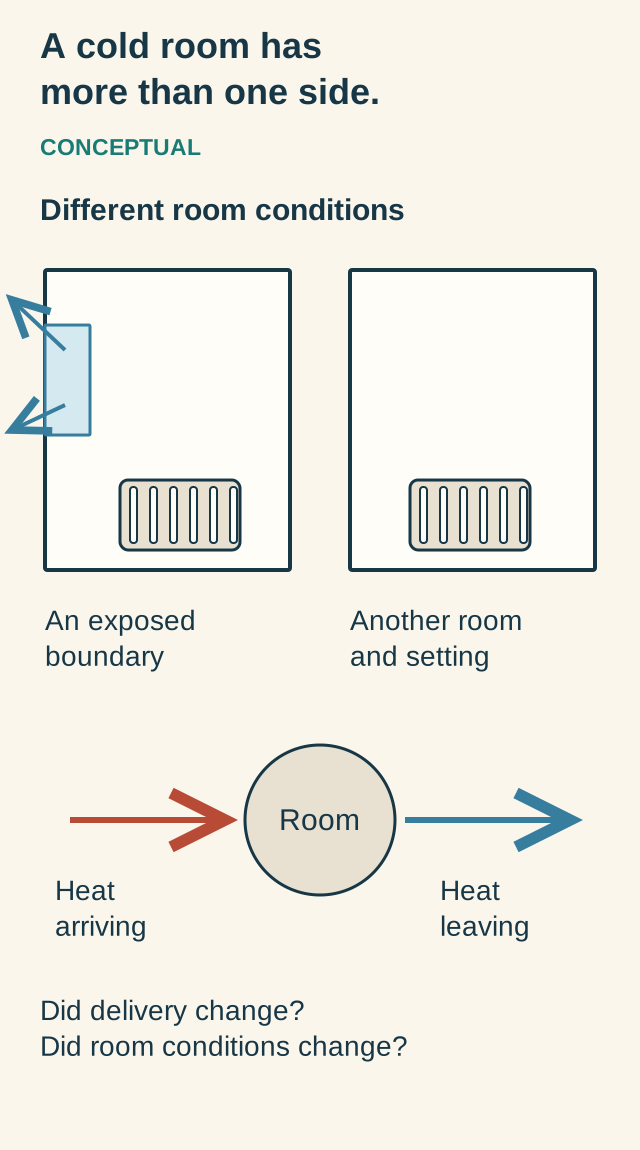
A cold room has more than one side.
An emitter supplies heat while the room loses heat. Exposure, use and other conditions help frame the assessment; similar-looking emitters do not establish identical room requirements.
Choose a part name to highlight its explanation below.
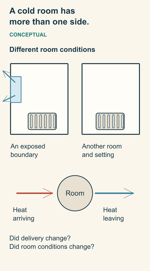
- Delivery
Source, circulation and emitter conditions determine the assessed heat arriving.
- Room conditions
Exposure, enclosure and ordinary use can influence the room’s requirement.
- Comparison
A corner/exposed room and another room are not assumed to be identical loads.
- Scope
Arrows are not scaled heat-loss results. A room design and an equipment service answer different questions.
A cold room has more than one side.
An emitter supplies heat while the room loses heat. Exposure, use and other conditions help frame the assessment; similar-looking emitters do not establish identical room requirements.
- Delivery
- Source, circulation and emitter conditions determine the assessed heat arriving.
- Room conditions
- Exposure, enclosure and ordinary use can influence the room’s requirement.
- Comparison
- A corner/exposed room and another room are not assumed to be identical loads.
- Scope
- Arrows are not scaled heat-loss results. A room design and an equipment service answer different questions.
Read all the diagram text
- A cold room has more than one side.
- CONCEPTUAL
- Different room conditions
- An exposed boundary
- Another room and setting
- Room
- Heat arriving
- Heat leaving
- Did delivery change? Did room conditions change?
Which conditions need prompt assistance?
Visible leakage, loss of essential heat during severe weather or an unsafe hot-surface concern needs timely appropriate assistance. If water may contact electrical equipment, keep clear rather than approaching a pump, control or panel to investigate. An active hazard takes priority over collecting a longer comfort log.
If a carbon-monoxide alarm sounds, leave immediately and call emergency services from outside. Do not search for a cause, investigate the heat source or wait for an online response. Return only after the problem has been resolved as directed by the appropriate professionals.
A hydronic distribution system does not by itself identify a combustion appliance, but a fuel-burning source has its own safety responsibilities. Keep the actual source’s instructions and service information with the system. A warm floor, working pump or quiet boiler does not override an alarm.
For an unfamiliar control warning, follow the exact equipment’s ordinary response instructions and contact the appropriate qualified provider. Do not repeatedly reset a fault, force a valve, bypass a control or refill the system to make a warning disappear.
What should a repair or renovation scope explain?
A useful scope begins with the question being addressed: source operation, control sequence, circulation, emitter condition, floor construction or room heat loss. Ask which finding supports the proposed work and which remaining questions are outside that appointment.
For concealed-floor work, establish the actual method before choosing access or a repair. Slab tubing, an overpour, dry panels, contact plates and suspended tubing put the heater in different places. A method appropriate to one is not automatically suitable for the others.
Electrical, plumbing, heating, floor and structural responsibilities may need coordination. If a finish, topping, panel or ceiling is disturbed, ask who restores the affected construction and how the system will be assessed after the actual work. A pipe repair and a completed suitable floor are related but separate tasks.
Installation and commissioning information can help later assessment. An old pressure test records that named test at its date; it does not establish that concealed tubing survived every subsequent fastening or renovation. Keep interpreted professional results rather than filling missing entries from a design drawing.
A proposed control or source replacement should address compatibility with the parts that remain. If the original complaint concerns a cold room, ask how the recommendation connects to that room and which follow-up will assess the stated goal. A short warm run is not a certificate for every circuit.
Local trade authorization, permits and responsibilities depend on the work and location. Confirm them with the applicable authority and actual qualified provider. A manufacturer handbook describes its equipment and methods; it does not establish an unidentified person’s credentials or permission for this home.
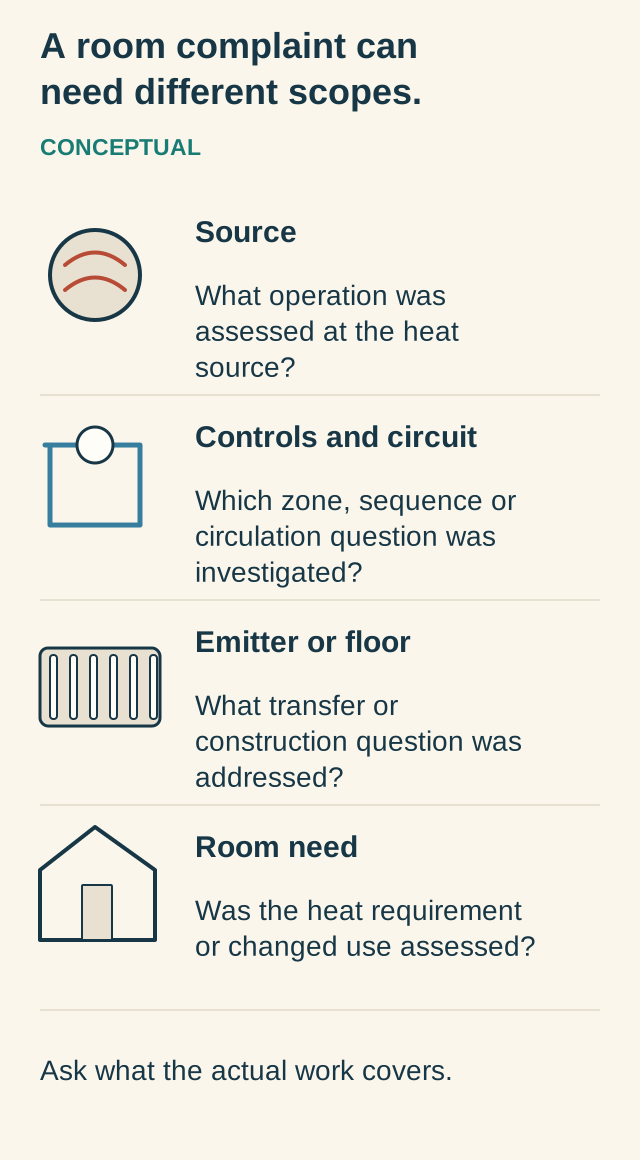
A room complaint can need different scopes.
Source operation, control/circuit behaviour, emitter construction and room need are different assessment scopes. Ask the provider to connect the actual finding and work to the original concern.
Choose a part name to highlight its explanation below.
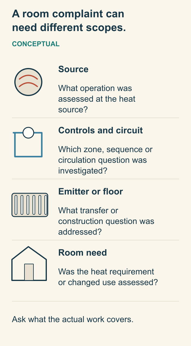
- Source
What was assessed about the actual heat source and under which conditions?
- Control and circuit
Which room/zone relationship, operating sequence or circulation question was investigated?
- Emitter and floor
Which radiator, baseboard, fan-coil or floor-transfer/assembly issue was addressed?
- Room and follow-up
Was the room requirement assessed, what work was completed and what question remains? No result is invented.
A room complaint can need different scopes.
Source operation, control/circuit behaviour, emitter construction and room need are different assessment scopes. Ask the provider to connect the actual finding and work to the original concern.
- Source
- What was assessed about the actual heat source and under which conditions?
- Control and circuit
- Which room/zone relationship, operating sequence or circulation question was investigated?
- Emitter and floor
- Which radiator, baseboard, fan-coil or floor-transfer/assembly issue was addressed?
- Room and follow-up
- Was the room requirement assessed, what work was completed and what question remains? No result is invented.
Read all the diagram text
- A room complaint can need different scopes.
- CONCEPTUAL
- Source
- What operation was assessed at the heat source?
- Controls and circuit
- Which zone, sequence or circulation question was investigated?
- Emitter or floor
- What transfer or construction question was addressed?
- Room need
- Was the heat requirement or changed use assessed?
- Ask what the actual work covers.
How do a different heat source and running costs change the decision?
The floor or radiator distributes heat; the source supplies it. A boiler, suitable heat pump or another designed source can lead to different operating conditions. Natural Resources Canada describes water as a possible heat-pump sink for hydronic distribution, but the actual system and climate still need assessment.
A change in supply conditions changes what an existing emitter can deliver. Panel size, fin-tube design, coil performance, floor layers and room demand therefore matter when a different source is proposed. It is not enough to count the current radiators or assume that all of them must be replaced.
The right comparison is a complete system at its intended operating conditions. A lower-temperature design may need a different emitter arrangement or other work; a particular existing emitter may already suit the assessed need. The designer should show the basis rather than rely on a generic rule about old and new heating.
Distribution choices also have different construction consequences. A dry panel avoids a wet topping, a below-floor method depends on access, and an exposed emitter uses room space. Their practical attractions and constraints are not the same as the heat source’s efficiency.
A useful operating-cost comparison needs the source, building demand, actual use and controls, fluid and distribution arrangement, and applicable energy tariffs. Heat stored in a slab or a manufacturer’s attractive product picture is not a saving calculation. No national price, payback or universal percentage is supplied here.
Ask which alternatives were considered, what work each includes and what performance question the design answers. If another heat source is being removed or a room use changes, retain that intended goal explicitly. A successful maintenance visit for the old system is not a new heating design.
What are the most useful questions to keep with the system?
“What is the actual source, and how does the heated fluid get to this room and back?” Start with that complete route. Then identify the emitter and, for a floor, the actual construction. The answer should name familiar parts and explain their jobs before asking you to interpret numbers.
“Which thermostat, rooms and loops belong together?” Keep the confirmed relationship beside any uncertain old label. A map is most useful when it distinguishes what was actually identified from a route still needing clarification.
“Does this work concern the source, controls, flow, emitter or the room’s heat requirement?” Ask that when a quote or report is vague. The useful explanation connects the finding to the proposed work, rather than treating a boiler invoice as proof of every room’s delivery.
Keep the actual product identities, manuals, floor/loop layouts, relevant construction photographs and interpreted service or commissioning records together. Add changed coverings, controls, emitters and room use without erasing the original history. An owner, buyer or seller can use the same clear account while preserving its actual scope.
You do not need to become a heating designer to understand your home better. Recognize the source, the moving-fluid route, the room emitter and the control relationship. Then ask for the missing explanation or appropriately scoped professional assessment, with no invented diagnosis or promise that one test proves the whole house.
Keep learning about the connected parts
Canadian context and authorities · Visual atlas · Learning labs
Know the parts.
Know what the words mean.
- Hydronic distribution
- Transport of heat through a circulating-fluid arrangement to room emitters, distinct from forced-air duct distribution.
- Emitter
- The component or heated assembly that transfers supplied heat into a room, such as a radiator, baseboard or floor arrangement.
- Control zone
- An area governed by a stated control relationship; its boundary need not equal one room or one water loop.
- Series loop
- A route in which fluid passes through successive emitters before returning; the actual installed arrangement must be established.
- Heat request
- A control demand interpreted using the actual device instructions, rather than a measured room-delivery result.
- Thermal response
- The change in room or assembly conditions over time, influenced by stored energy, delivery, losses and controls.
- Overpour
- A separately specified poured layer containing tubing above a supporting deck in the illustrated floor arrangement.
- Heat-transfer plate
- A metal component spreading heat from tubing toward the floor; the named underfloor example contacts the underside of the subfloor.
- Manifold
- An assembly that distributes supply fluid into branches and collects returns in the illustrated arrangement.
- Actuator
- The mechanism operating a compatible control valve; distinct from a circulator moving fluid.
- Fan-coil
- An emitter using a fan to move room air across a coil supplied with heating fluid.
- Heat source
- The equipment or designed arrangement supplying heat to the distribution fluid, distinct from the floor or radiator releasing it into the room.
- Contact-plate method
- The named below-subfloor arrangement in which the tubing and plate provide a contact heat-transfer route into the timber floor.
- Suspended-tube method
- The separately specified below-subfloor arrangement holding tubing on clips with an intentional airspace, rather than plate contact.
Questions to bring
to the conversation.
- What source and distribution arrangement are actually installed?
- Which floor construction or room emitter is being discussed?
- How do the actual thermostat, rooms, loops and controls relate?
- What changed under ordinary conditions, and which professional finding addresses it?
- Does the proposal include source, control, circulation, emitter/floor and room-load responsibilities as needed?
Separate a showing observation, an existing record and a new professional assessment. Unknown means a question remains; it does not automatically mean a defect.
Use the evidence planner ↗Go to the source.
Original HomeAI explanation informed by these public references. Sources support the underlying guidance; they have not reviewed or endorsed HomeAI. Diagrams are conceptual, and calculator outputs depend on your inputs.
Canadian home-heating education, with product-specific examples qualified separately. Primary readings, editions, geography and reading limits are recorded with each reference. Illustrations explain recognizable parts and mechanisms; actual design, condition and repair decisions need the appropriate qualified professional.
Publication & source review
First published .
Sources reviewed .
- Natural Resources Canada · Heating with Gas, revised October 2012
Where this reference applies
Jurisdiction: Canada; older federal educational description of gas-fired and circulating-water systems
PDF pages 2, 15–16 and 24–25: printed October 2012 edition; generation, circulation, room emitters, radiant-floor arrangements and series-loop distinction. Exact publication day is unknown. Old prices, savings, temperatures, retrofit prescriptions and valve/balancing instructions are excluded. The described mechanisms do not establish a current approved installation.
- Natural Resources Canada · Keeping the Heat In, section 9: operating your house
Where this reference applies
Jurisdiction: Canada; general homeowner education with equipment-dependent exceptions
Publisher publication date: 2014-03-06
Publisher modification date: 2025-09-29
Sections 9.1.2–9.1.3: some hydronic systems have slower response, and generation/distribution/building loads require distinct assessment. No universal setback, savings, equipment sizing, bleeding, pressure, damper or water-temperature procedure is adopted.
- Watts / tekmar · Switching Relay 304P Installation & Operation Manual, 304P_D 02/20
Where this reference applies
Jurisdiction: Manufacturer model 304P example; installed identity and configuration must be confirmed
PDF pages 1–2 and 7, printed February 2020 edition: thermostat calls, zone indicator meaning, optional domestic-hot-water priority and post-purge. Exact publication day is unknown. This example does not describe every control. Wiring, voltages, terminals, fuses, DIP switches, timing settings and owner service procedures are excluded.
- Health Canada · Carbon monoxide: preventing exposure
Where this reference applies
Jurisdiction: Canada; immediate CO response and Canadian-certified alarm guidance
Publisher publication date: 2024-11-12
Publisher modification date: 2024-11-12
CO-alarm evacuation, outside emergency contact, professional resolution before return and certification/manufacturer instructions. Consumer indoor-air trend readings cannot override an alarm or authorize re-entry. No alarm-law claim for every province or combustion testing procedure is supplied.
- Uponor · Residential Radiant and Hydronics Installation Handbook, 7th edition December 2023
- Uponor · XpressTrak Installation Guide
- Uponor · JoistTrak Heat Transfer Panel Handbook
- Caleffi · 8: Heat Emitter Options
- Caleffi · 3: Single-Circulator Distribution Systems
- Caleffi · idronics 35
- Natural Resources Canada · Heating and cooling with a heat pump
- Legalett · Air-heated floor and shallow-foundation FAQ
- Watts / tekmar · Switching Relay 304P Installation & Operation Manual
- Health Canada · Carbon monoxide: preventing exposure
- Electric-format contrast · fresh primary reading bundle
Have a question about your home?
Start with the symptom, timing and what you have observed.
Ask HomeAI